The information provided on this page is not of a regulatory
nature - it is for information purposes only.
 |
This is a *** DRAFT *** release of the loom to be used with
the M800 ECU from 2009 onwards.
Download the PDF file here (Last updated on 31 Oct 2008).
•Which connectors are used in the loom?
•May any of the sensor inputs be shared?
•How does the rain light get wired in?
•What about pull-ups and power supplies?
What connectors are used in the loom?
The spark sensor amplifier will be provided by MoTeC, but does not yet have a part number.May any of the sensor inputs be shared?
•May any of the sensor inputs be shared?
•How does the rain light get wired in?
•What about pull-ups and power supplies?
| # | Component | Connector Options |
| P7 | ECU - Lambda Connector | Deutsch AS0-12-98SN Deutsch AS1-12-98SN Souriau 8STA0-1298SN |
| Lambda - ECU Connector | Deutsch AS6-12-98PN Souriau 8STA6-1298PN | |
| P8 | ECU - Data connector | Deutsch AS0-10-35SN Deutsch AS1-10-35SN Souriau 8STA0-1035SN |
| Data - ECU Connector | Deutsch AS6-10-35PN Souriau 8STA6-1035PN | |
| P9 | ECU - Spark Sesnor Amplifier | Deutsch DTM06-12S-E007 |
| P20 | ECU - Chassis connector | Deutsch AS6-14-97PN Souriau 8STA-1497PN |
| Chassis - ECU Connector | Deutsch AS0-14-97SN Deutsch AS1-14-97SN Souriau 8STA0-1497SN | |
| P21 | ECU Comms connector | Deltron 716-0-0501 |
The spark sensor amplifier will be provided by MoTeC, but does not yet have a part number.
The following sensor inputs may be shared:
(The sharing is not mandatory as the signals will also be available over the CAN bus)
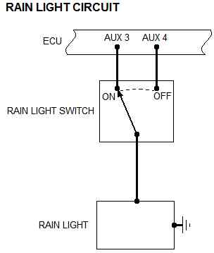
How does the rain light get wired in?
(The sharing is not mandatory as the signals will also be available over the CAN bus)
| • Front Road Speed |
| • Front Brake Pressure |
| • Steering Position |
| • Gear Position |
When activated, the Pit Limit Switch input will cause both outputs (Aux3 and Aux4) to flash.
What about pull-ups and power supplies?
 |
No pull-up resistors will be required on any sensor or other input.
The lambda sensors may be powered from a Power Control Module (PCM) with the Heater Control signals serving as inputs to the PCM.
The powering of any sensors that is not clearly defined by the loom schematic is free at this point in time.
The lambda sensors may be powered from a Power Control Module (PCM) with the Heater Control signals serving as inputs to the PCM.
The powering of any sensors that is not clearly defined by the loom schematic is free at this point in time.

 Home
Home