Summary
This sensor was designed specifically for the motor racing
industry. It meets the demands of the harsh environment experienced
in modern motorsport. One particular application of the sensor (in
the Australian V8 Supercar seires) has seen these sensors do four
seasons of service - their prior sensors only managed about nine
months of service before failing due to vibration.
The sensor is a three-axis (X, Y, Z) sensor with each axis orthogonal to the
others, measuring positive and negative forces in each of the 3 axes.
The development of this sensor had the following design goals:
- G-Force, Gyroscopic & Magnetic Sensing
- Triple axis sensing of all parameters
- CAN Bus Output - due to the number of data channels
- High level of customisation of the data output
- Flexible CAN bus address and data rates
- Rugged design
- Cost competitive
History
Jacobs Design has had a long involvement with the Australian V8 Supercars
in a scrutineering role primarily focused on the electronic and data
acquisition systems. The use of gyros had for a long time been banned
from V8 Supercars due to their expense and the level of expertise required
by data engineers in the analysis of the data gathered by these sensors. In
the current era, all V8 Supercars teams have access to excellent data engineers.
The 3Force sensor was developed in late 2011, following on from many years of
successful use of the g-force sensors in the
motorsport environment. Building from the mechanical reliability of the
g-force sensor, the 3Force sensor is a
technological leap, incorporating gyroscopic as well as magnetic sensing in
the same housing as the original sensor.
General Specifications
| Parameter | Minimum |
Typical | Maximum | Units | | CAN Speed (See note 1) | 125K | -
| 1M | baud | | Supply Voltage (See notes 2, 3) | 6 | -
| 24 | V Sensor Supply | | Supply Current | - | 20
| 40 | mA | | Operational Temperature | -20 | -
| 70 | degrees C | | | | Weight | <55 grams (including pigtail) | | Enclosure Material | Aluminium 6016-T6 (Anodised) | | Heatshrink | Raychem DR-25 | | Connector Wire | Mil-W-22759/16 | |
G-Force (Acceleration) Sensor
| Parameter | Minimum |
Typical | Maximum | Units | | Measurement Range (16g option) | - | 16
| - | g | | Stability | - | +/-0.015
| - | % per degree C | | Nonlinearity | - | +/-0.3
| - | % | | Inter-Axis Alignment Errors | - | +/-0.1
| - | % | | Cross-Axis Sensitivity | - | +/-1
| - | % | | CAN Bus Rate | 1 | 50
| 500 | Hz | | | | Reported Resolution | 1 milli-g (1000 counts per 1g) | |
Gyroscopic (Rotation) Sensor
| Parameter | Minimum |
Typical | Maximum | Units | | Measurement Range | - | 500
| - | degrees per second | | CAN Bus Rate | 1 | 50
| 500 | Hz | | | | Reported Resolution | 0.1 degrees per second | | Internal Sample Rate | 800 Hz | |
Magnetic (Compass) Sensor
| Parameter | Minimum |
Typical | Maximum | Units | The sensor is capable of detecting the earths magnetic field,
although it is affected by the presence of ferrous objects at
very short range.| CAN Bus Rate | 1 | 20
| 100 | Hz | | | | Internal Sample Rate | 75 Hz | |
Notes:
- The CAN bus speed is selected when the sensor is purchased.
The CAN bus speed may be changed at a later stage.
- DO NOT connect the sensor directly
to the vehicle battery. The sensor is not capable of dissipating
the energy caused by load dump conditions.
- The sensor will typically operate down to a supply voltage
of 4.2V. However, as the supply voltage gets lower the quality
of the supply becomes increasingly critical. In vehicle powered
systems it is not recommended to go below 5V supply, in addition,
if the sensors suffers from drop-outs at these levels then some
form of voltage buffering or extra capacitance may be required
at the sensor.
Wiring the 3Force Sensor
The sensor requires a supply voltage of 5 to 24 Volts, which must be from a
protected source.
DO NOT connect the sensor directly to the
vehicle battery.
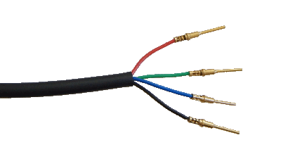
The 3Force outputs are generated as messages on the CAN bus. Their is no CAN
termination resistor in the sensor. The sensor is supplied with a pigtail loom.
 |
Red - Supply Voltage (5V to 24V)
Green - CAN High / CAN +
Blue - CAN Low / CAN -
Black - 0V / Chassis |
Mounting the 3Force Sensor

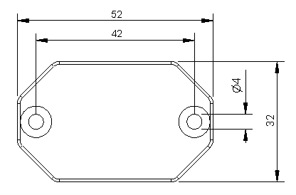
(all dimensions in mm)
Flexible Mounting
Double sided tape or Velcro may be used to mount the sensor when an amount of
"shock filtering" is required.
Rigid Mounting
M4 countersunk bolts may be used to mount the sensor when a more direct
coupling is required. Excessive vibration "may" swamp the g-force measurements.
However, this method of mounting has proven successful in a V8 Supercar (with the
sensor mounted to the driveshaft tunnel).
Rigid mounting is recommended for the 100g sensor.
The top view of the accelerometer is as follows:
Available Downloads
Configuring the Data Aquisition System
Refer to the document
3Force Data Sheet
for further details on how to configure your data acquisition system (abbrev. DAS).
Calibrating the 3Force Sensor
There are two methods that may be used to calibrate the 3Force sensor. A software
compensation may be applied in the DAS, or the sensor can have its calibration
updated.
Software Compensation
In the CAN bus template of the DAS, there would normally be factors for
converting the sensor value from an integer value (as transmitted by the sensor)
to a floating point value (as used by the DAS). These compensation values,
typically just simple offset and magnitude numbers, may be adjusted to
effectively calibrate the equipment without needing any special know-how.
Sensor Calibration
The
3Force Data Sheet documents all
the CAN messages required to calibrate the sensor.
PLEASE NOTE: Due to global silicon shortages, we are currently unable to supply this sensor. Projected availability is currently for December 2021.
|
|
|
Notes
1) The G-Force Bandwidth is set in hardware and sealed
into the sensor, and NOT able to be changed once the sensor has been
shipped. The default value has been selected as the best all round compromise
between sensor measurement range, sensitivity and vibrational noise immunity.
2) All the other parameters are able to be set to different values at a later
date. However, a CAN interface device is required to change the sensor
settings, so choose wisely if you want to get started with the sensor without
too much delay.
Commercial Terms
• Price includes postage - local and international
• Price includes GST - for Autralian customers
• Import duties and taxes are the responsibility of the purchaser
• All sensors come with a 12 month warranty
• Discounts apply for bulk purchases -
contact us for further details. |
